본문
5015 Style
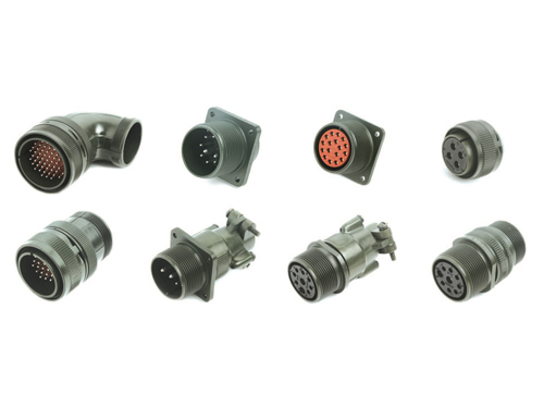
이 커넥터는 원래 군용 장비에 사용되도록 디자인 되었으나, 현재는 여러 산업분야에서 사용되고 있습니다. 특히 높은 신뢰성이 요구되는 산업제품인 각종 의료장비, 전기자동차, 산업용공작기계, 로봇 등에 저렴한 가격으로 적용되고 있습니다. 커넥터의 결합방식은 나사식 결합방식이며, 커넥터의 전선과 접점 연결방식은 납땜형입니다. CLASS“A”,“B”형은 방수가 되지 않는 제품이며, CLASS “E”,“F”,“R”형은 절연체 패킹을 포함하여 커넥터 후면의 전선부를 방수 할 수 있도록 하였고, YH3106/YH3108 플러그 커넥터의 CLASS “F”,“R”형은 오링을 포함하여 커넥터 전면부에 대한 방수가 가능하도록 제작되었습니다. 이 커넥터의 상호 결합 관련 치수 및 접점배열은 MIL-DTL-5015 규격과 일치합니다.
품명구성 (Ordering Information)
Military Nomenclature

- YH Number Shell Style
-
YH3100 - Wall Mounting Receptacle
YH3101 - Cable Connecting Plug
YH3102 - Box mounting Receptacle
YH3106 - Straigt Plug
YH3108 - 90°Angle Plug - Class
-
A - Solid shell for general, non-environmental applications
E - With resilient insulator and integral clamp for cable strain relief
F - Same as E, However style 3106 with O-ring seal under the coupling nut
R - With resilient insulator and shortened, lightweight endbell
(additional sealing with O-ring under the coupling nut for shell styles 3106 and 3108) - Shell Size
-
10SL, 12S, 12, 14S, 14, 16S, 16, 18, 20, 22, 24, 28, 32, 36
- Contact Arrangement
-
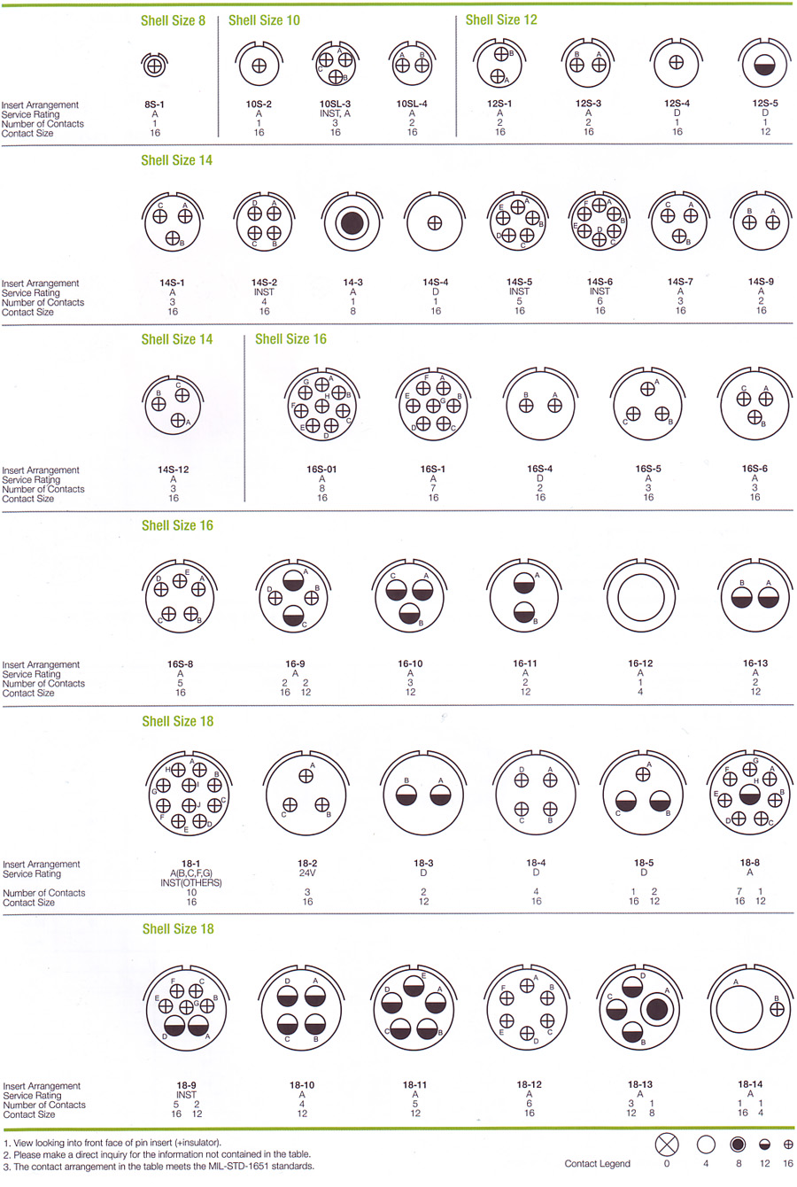
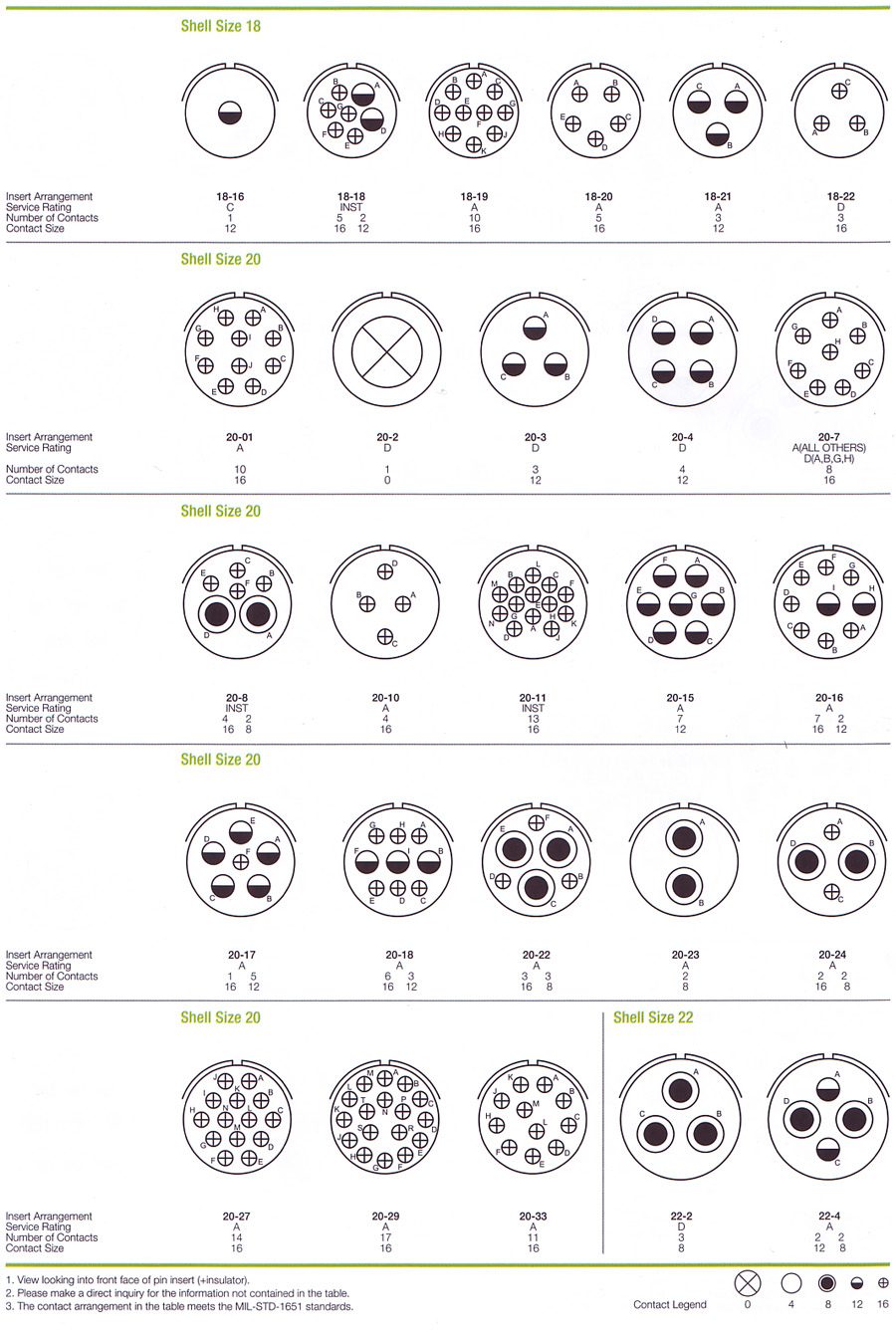
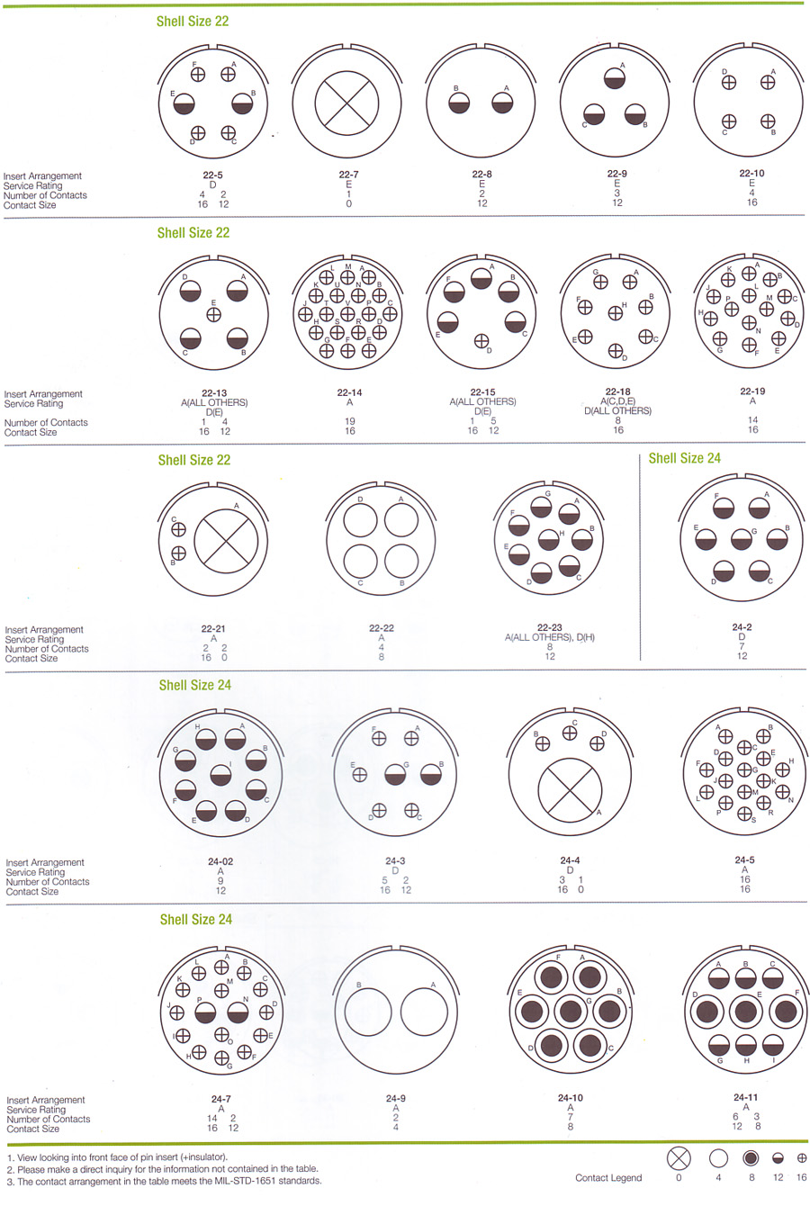
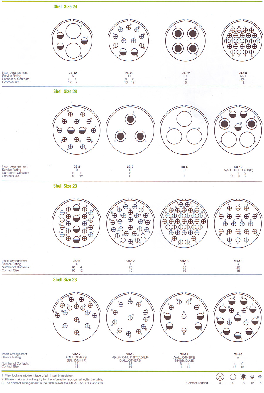
MIL-STD-1651에 따른다.
- Contact Style
-
P - Pin Contact
S - Socket Contact - Alternate Insert Position
-
N(Normal), W, X, Y, Z(MIL-STD-1651)
- Finish
-
BLANK - Conductive Olive Drab Chromate Over Cadmium or Zinc plate.
01- Black Anodize
02- Electroless Nickel plate
03- Black Zinc Cobalt Plate
Yeonhab Nomenclature

- YH Number Shell Style
-
YH3100 - Wall Mounting Receptacle
YH3101 - Cable Comnnecting Plug
YH3102 - Box mounting Receptacle
YH3106 - Straigt Plug
YH3108 - 90°Angle Plug - Class
-
A - Solid shell for general, non-environmental applications
E - With resilient insulator and integral clamp for cable strain relief
F - Same as E, However style 3106 with O-ring seal under the coupling nut
R - With resilient insulator and shortened, lightweight endbell
(additional sealing with O-ring under the coupling nut for shell styles 3106 and 3108) - Shell Size
-
10SL, 12S, 12, 14S, 14, 16S, 16, 18, 20, 22, 24, 28, 32, 36
- Contact Arrangement
-
MIL-STD-1651에 따른다.
- Contact Style
-
P - Pin Contact
S - Socket Contact - Alternate Insert Position
-
N(Normal), W, X, Y, Z(MIL-STD-1651)
- Finish
-
BLANK - Conductive Olive Drab Chromate Over Cadmium or Zinc plate.
01- Black Anodize
02- Electroless Nickel plate
03- Black Zinc Cobalt Plate
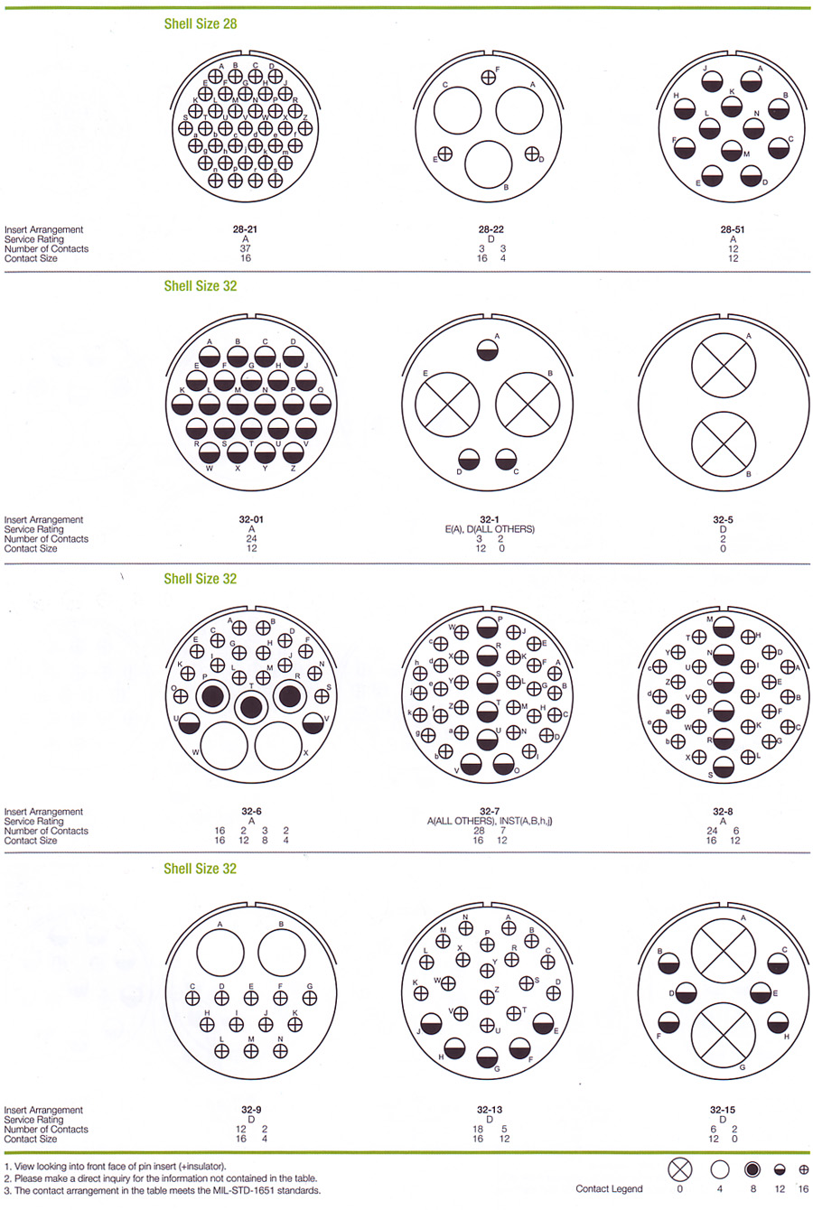
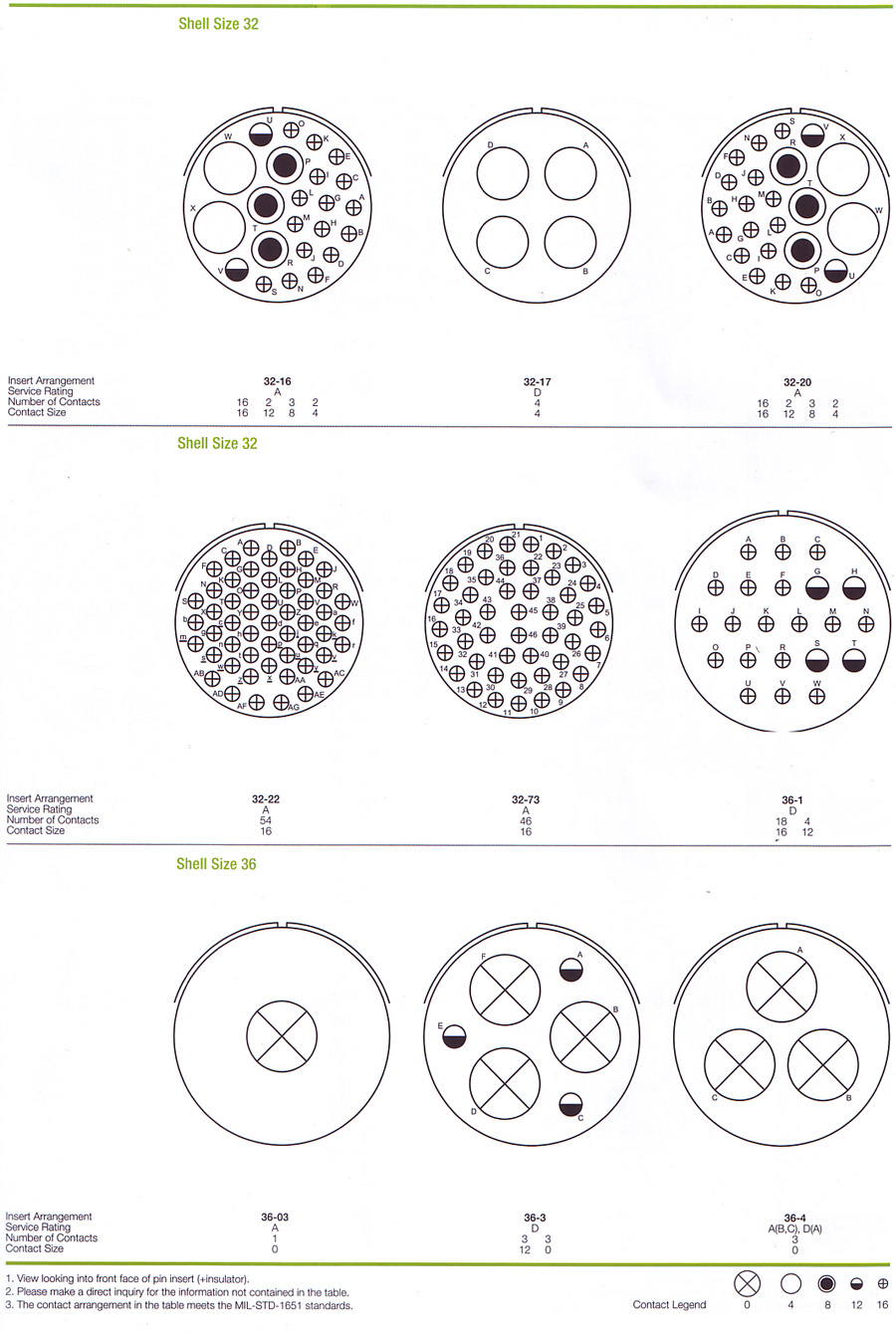
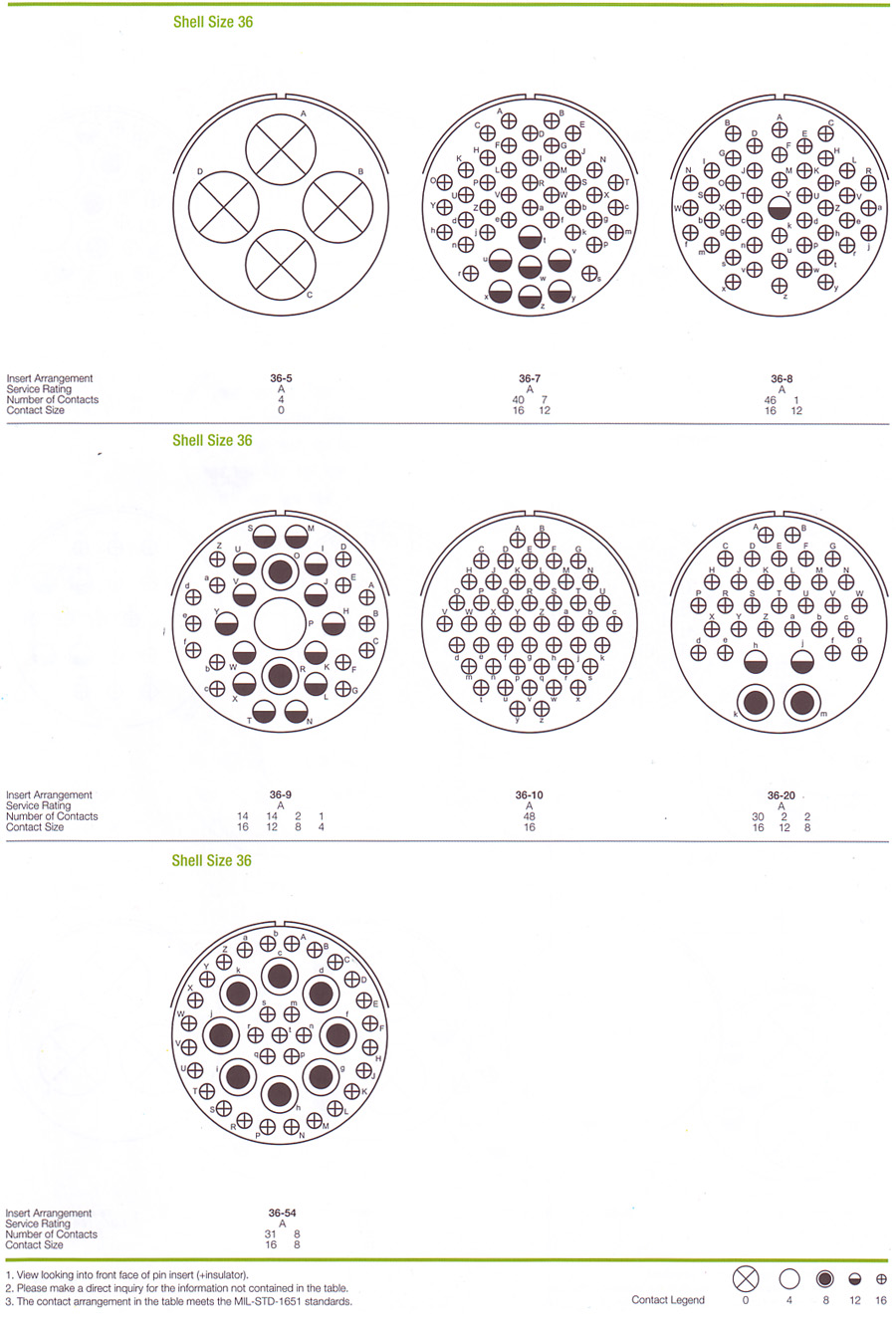
결합안내 (Mating Face View)

기술적 정보 (Technical Data)
표준 재질 및 보호피막 (Standard Materials and Finishes)
| Portion | Materials | Finishes |
|---|---|---|
| 몸체(Shell) | Aluminum alloy | Olive drab chromate coating over cadmium or zinc plating. |
| 절연체(Insulator) | Polychloroprene (resilient) | - |
| 접점 (contacts) | Brass or Copper alloy | Silver plate |
전기적 특성 (Electrical Data)
| 절연저항(Insulation Resistance) | 5 000 MΩ Min.(at 25 ℃) |
|---|---|
| 사용온도범위(Operating Temperature Range) | -55 ℃ ~ 125 ℃ |
| 내구성(Durability) | 500 cycle, mate and unmate |
접점배열 서비스 등급 (Contact Arrangements Service Rating)
| Dielectric Withstanding Voltage | Contact Engaging & Separating Force | ||||||
|---|---|---|---|---|---|---|---|
| Service Rating | Test Voltage AC(rms) | Operating Voltage | Contact Size | Force in Lbs | |||
| AC (rms) | DC | Maximum | Average | Minimum | |||
| inst. | 1,000 | 200 | 250 | 16 | 3.00 | 2.06 | 0.13 |
| A | 2,000 | 500 | 700 | 12 | 5.00 | 3.50 | 0.19 |
| D | 2,800 | 900 | 1,250 | 8 | 10.00 | - | 0.31 |
| E | 3,500 | 1,250 | 1,750 | 4 | 15.00 | - | 0.63 |
| B | 4,500 | 1,750 | 2,450 | 0 | 20.00 | - | 0.94 |
| C | 7,000 | 3,000 | 4,200 | ||||
Altitude Voltage Derating Chart
| Service Rating | Nominal Distance |
Standard Sea Level Conditions |
Pressure Altitude 70,000 ft |
|||
|---|---|---|---|---|---|---|
| Airspace | Creepage | Minimum Flashover Voltage AC(rms) |
Test Voltage AC(rms) |
Minimum Flashover Voltage AC(rms) |
Test Voltage AC(rms) |
|
| inst. | 1/32 | 1/16 | 1400 | 1,000 | 325 | 260 |
| A | 1/16 | 1/8 | 2800 | 2,000 | 450 | 360 |
| D | 1/8 | 3/16 | 3600 | 2,800 | 500 | 400 |
| E | 3/16 | 1/4 | 4500 | 3,500 | 550 | 440 |
| B | 1/4 | 5/16 | 5700 | 4,500 | 600 | 480 |
| C | 5/16 | 1 | 8500 | 7,000 | 700 | 560 |
| Contact Size |
Pin Contact Dia. |
Solder Pot Dia. |
Current(A) Rating (Mated With Insulators) |
Contact Resistance | Wire Range Accommodations | |||
|---|---|---|---|---|---|---|---|---|
| Test Current (A) |
Potential Drop Max(mV) |
Wire Size (AWG) |
Wire Normal Square Size(㎟) |
Dielectric Material Outer Dia. |
||||
| 16 | 1.6 | 2.0 | 13A | 20A | 21 | 16~22 | ≤ 1.3 | 1.7~3.3 |
| 12 | 2.4 | 3.0 | 23A | 35A | 20 | 12~14 | ≤ 3.5 | 2.9~4.3 |
| 8 | 3.6 | 5.2 | 46A | 60A | 12 | 8~10 | ≤ 8.0 | 4.2~6.4 |
| 4 | 5.7 | 8.5 | 80A | 110A | 10 | 6~4 | ≤ 22.0 | 7.0~9.4 |
| 0 | 9.1 | 12.0 | 150A | 200A | 10 | 0~2 | ≤ 50.0 | 10.6~14.0 |
5051 Style 접점배열도
